The Cleary Building
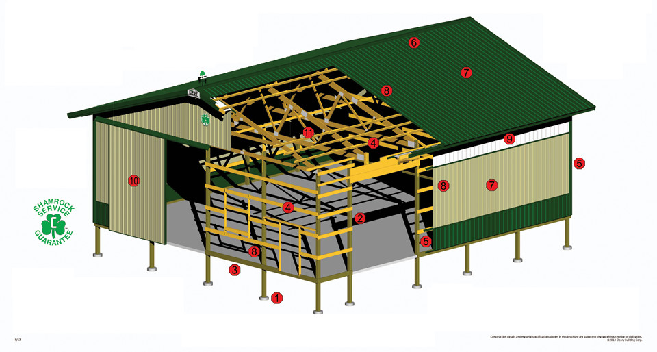
The Cleary Building Rendering:
Here you can learn about the eleven main components that make up a Cleary Building. These components include the footings, treated non-spliced 3-ply columns, treated splash plank, framing lumber, trim, closure strips, roofing and siding, fasteners, light panels, slide doors and trusses.

Precast 4″ thick footing pad is provided under all structural columns. Foots shall be placed below the frost penetration level, but in no case less than 46″ below adjacent ground.
The structural columns shall be a nail-laminated assembly consisting of a maximum of three plies of #1 Southern Pine 2×6 or 2×8 lumber treated in accordance with the American Wood Preservers Association Standard, Latest Edition. The outer plies of Columns that are 24′ long or less shall extend without a splice from the footing to the eave height.
A 2×8 Southern Yellow Pine or better splash plank shall extend around the perimeter of the building. All lumber in contact with the ground shall be pressure treated in accordance with the American Wood Preservers Association Standard, Latest Edition.
All structural framing lumber shall be #2 or better S4S material and shall bear a stamp indicating species and grade. Material shall be kiln dried to a moisture content of 19% or less.
Roofing and siding panels shall be covered with prepainted galvanized steel trim at all corners, ridge line, intersection of roof and endwalls, intersection of roof and sidewalls and bottom of sidewall steel.
All closure strips shall be laminated polythylene with dovetail end joint; shaped to conform with the roofing and siding profile. Closure strips shall be placed on each side of the ridge, between the ridge cap and roof panel.
Roofing and siding material shall be prepainted 29 gauge, 100,000 PSI nominal tensile strength bare structural steel. The panel shall be formed with major structural ribs at 9″ o.c. Panels shall be 36″ wide to minimize side laps. Roof panels shall be continuous, without end laps, from eave to ridge line; sidewall and endwall shall be continuous without endlap from treated splash plank to the roofline.
Roof and sidewall steel panels shall be attached to framing using color matched galvanized screws with a 1/4″ hex-head and an EDPM flat bonded sealing washer. Sidewall girts and framing shall be attached to the treated columns with hot dipped galvanized 20d ring shank nails, constructed of quenched, hardened steel or 3.5″x.131″ diameter ring shank TLN power driven nails.
All roof and sidewall light panels shall be SunSky corrugated polycarbonate panels, and the panels shall be of the same configuration as the roofing and sidewall panels. Eavelite, Skylite, and Ridgelite shall be White Opal with 45% light transmission and Solar panels shall be Clear with 90% light transmission.
All slide doors shall be constructed with steel horizontals and verticals and covered with steel panels of the same type as that of the sidewall panels. Both vertical and horizontal members shall be a minimum of 16 gauge steel and not less than 2 1/2″ deep. Each door leaf shall be supported with one pair of trolley hangers, which shall ride in an overhead track. Door track shall be 14 gauge; high carbon galvanized steel self cleaning and self aligning supported with galvanized brackets 24″ o.c. Trolleys shall have wheels made of Delrin 500R with teflon lubrication. Bottom of doors shall be secured when in the open position with galvanized steel guide rail of a length not less than 60% of the width of the door leaf.
All lumber used in the design and construction of wood trusses shall be kiln dried and graded in accordance with current grading rules. Design stresses shall not exceed those listed in the Latest Edition of National Design Specification, Wood Construction and its supplement. Truss plates shall be galvanized steel. Plate and joint design shall conform to the specification as set forth in the latest edition of the Truss Plates Institute’s Design Specifications for Metal Plate Connection Wood Trusses. All truss designs must be accompanied by complete drawings bearing the seal of the registered design architect or engineer. Trusses shall bear on the center ply of the laminated column and shall be sandwiched between the outer column plies. Trusses shall be nailed and bolted to the columns.
